Luis Hoyos is a fresh graduate Mechanical Engineer with thermodynamics and fluids mechanics expertise. He's interested in learning new things and applying them to real-life problems. Luis also likes to build tools that make repetitive and boring tasks a breeze, like calculators (surprise?). When he's not creating calculators, he's in the process of building the size of the tissue attached to his bones, aka bodybuilding. He also loves being with his little cat and seeing her do crazy things. See full profile
Reviewed by Steven Wooding
Physicist holding a 1st class degree and a member of the Institute of Physics. Creator of the UK vaccine queue calculator, and featured in many publications, including The Sun, Daily Mail, Express, and Independent. Tenacious in researching answers to questions and has an affection for coding. Hobbies include cycling, walking, and birdwatching. You can find him on Twitter @OmniSteve. See full profile
Based on 2 sources
10 people find this calculator helpful
Table of contents
This shear stress calculator calculates the shear stress due to transverse loads and the shear stress due to torsion (torque) applied on a circular shaft.
The shear stress from transverse forces is critical in the design of thin-walled members. For non-tin-walled members subjected to transverse loads, the most important is usually the axial stress caused by the bending moment. Our stress calculator can also be helpful if you're dealing with axial stress. If that's not the case, use this calculator!
The shear stress equation to use will depend on whether we apply a transverse load to a beam or a torsion couple to a circular shaft. In the following sections, you can look at the formulas for shear stress under these two conditions. We'll show how to calculate the maximum shear stress for many beams and how to calculate the stress at any point.
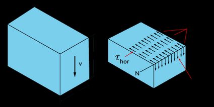
By definition, shear stress is force acting tangent to an area. In a beam of cross-sectional area A A A subjected to a shear force ( V V V ), the average shear stress ( τ avg \tau_\text τ avg ) is:
τ avg = V A \tau_\textThis is just an average, as the shear stress across a beam subjected to transverse shear varies widely, and we usually need to know its maximum value instead of just the average.
You can find the exact shear stress at any vertical distance from the neutral axis with the following equation:
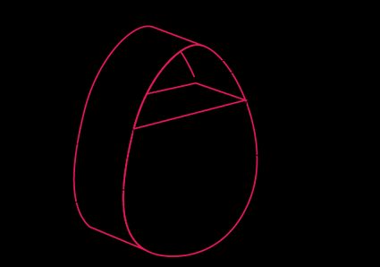
τ = V Q I t \tau = \fracQ Q Q is a tricky quantity. Mathematically, it is the area above the point of interest multiplied by the distance between the centroid of that area to the neutral axis. For example, for the cross-section of cam geometry below, if you wanted to calculate the shear stress at a distance y ′ y' y ′ from the neutral axis, the corresponding Q Q Q would be Q = y ˉ ′ A ˉ Q = \bar y' \bar A Q = y ˉ ′ A ˉ .
Using the shear formula ( τ = V Q / I t \tau = VQ/It τ = V Q / I t ) requires being careful about calculating the different quantities (especially Q Q Q ) and carefully inspecting the point of maximum shear stress ( τ max \tau_\text τ max ). For that reason, in this calculator, we included the possibility of obtaining τ max \tau_\text τ max for the most common shapes (rectangular, circular, and I-beams) by only inputting their dimensions and the shear force. You can look at those formulas in the table below (scroll to the right to look at them):
Maximum shear stress
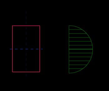
τ max = 3 V 2 A \tau_\text = \frac τ max = 2 A 3 V
A = d b A = db A = d b
Stress at distance y:
τ = 3 V 2 A ( 1 − y 2 ( d / 2 ) 2 ) \tau = \frac(1-\frac<(d/2)^2>) τ = 2 A 3 V ( 1 − ( d /2 ) 2 y 2 )
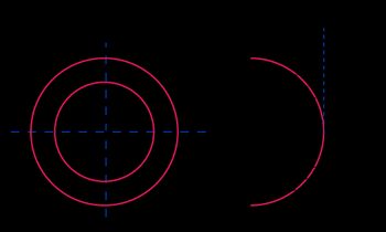
τ max = 4 V 3 A R 2 + R R i + R i 2 R 2 + R i 2 \tau_\text = \frac\frac^2>^2> τ max = 3 A 4 V R 2 + R i 2 R 2 + R R i + R i 2
A = π ( R 2 − R i 2 ) A = \pi(R^2 - R_i^2) A = π ( R 2 − R i 2 )
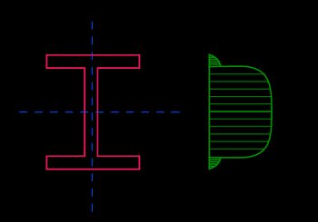
τ max = V 8 I x t ( b ( d + 2 t ) 2 − b d 2 + t d 2 ) \tau_\text = \frac \left(b(d+2t)^2 - bd^2+td^2\right) τ max = 8 I x t V ( b ( d + 2 t ) 2 − b d 2 + t d 2 )
τ min = V b 8 I x t ( ( d + 2 t ) 2 − d 2 ) \tau_\text = \frac \left((d+2t)^2 - d^2\right) τ min = 8 I x t Vb ( ( d + 2 t ) 2 − d 2 )
I = b ( d + 2 t ) 3 − ( b − t ) d 3 12 I = \frac I = 12 b ( d + 2 t ) 3 − ( b − t ) d 3
💡 In an I-beam (wide-flange beam), the τ min \tau_\text τ min value (the stress value at the joint between the flange and web) is a critical quantity, as sometimes the joint in that zone is created through welding or glue, and we need to calculate how much stress those elements will withstand.
To calculate the shear stress from a torque applied to a circular shaft, we use the torsional shear stress formula:
τ = T ρ J \tau = \fracThe maximum shear stress for torsional loads occurs at the outer surface of the circular shaft, where ρ = R \rho = R ρ = R . In other words, the maximum shear stress ( τ max \tau_\text τ max ) is given by:
τ max = T R J \tau_\textPlease keep this in mind: